Simple and Practical 150w Power Inverter Circuit
This is a kind of excellent performance power inverter for home circuit diagram, materials are easy to get, and the output power can reach 150W. This circuit is envisaged frequency in 300Hz. The purpose is to reduce the inverter transformer size and weight, output is square wave. The inverter can be used in home lighting, electronic ballasts for fluorescent lamps, and household appliances for switching power supply when the power fails. It is simple to make this power inverter for us.
For the 150 watt power inverter, capacitors C1, C2 use polyester capacitors, transistors BG1-BG5 can use 9013: 40V 0.1A 0.5W. BG6-BG7 can use FET IRF150: 100V 40A 150W 0.055 ohms. To not connect with power tube, measuring points A, B point voltage to ground, adjustment R1 or R2 to make A, B two points' voltage is the same, so that the output of the square wave is symmetrical and the static current is the least. Pay attention to the following items when assembling: it is necessary to use grounding high-quality electric iron or cut off the power before BG6, BG7 welding. Large current connection with more than diameters 2.5MM wire, and the connection as short as possible, battery voltage is 12V, capacity is above 12AH. Power tube need to be added the appropriate heat sink, for example, with 100×100×3MM aluminum plate heat dissipation. If you want to increase the power, more use the same model of power tube parallel, accordingly increase the power transformer.
Envisaged power inverter calculation method
The choice of transistor: in the thinking of safety will be the inevitable safety coefficient. Experience materials are as follows:
DC supply voltage: transistor collector-emitter withstand voltage BVCEO
6~8V≥20~30V
12~14V≥60~80V
24~28V≥80~100V
Calculation collector current of transistor:
ICM(A)=Output Power P(W)÷input voltage(V)×efficiency
The input voltage is power voltage. Efficiency is related with selection circuit, generally between 60 - 80%.
Core cross-sectional area:
S(cm²)=k×the square root of transformer rated power
Transformer core selection: amateur production is practical to transformer core. But the best selection to silicon is thin and crisp texture, or accepts the ferrite core. Enameled wire with high strength, winding required closely level wound with winding machine. It needs in strict formation when silicon is arranged. The relationship of low-level voltage across the winding with parameters of core cross-sectional area, inferior working frequency and so on can be formulated as follows:
V = 4.44 × 10⁻⁸SKFBN;
S --- Core cross-sectional area (square centimeters);
K --- Silicon gap coefficient (0.9 to 0.95);
F --- Inverter operation frequency (Hz);
B --- Saturation magnetic flux density (the T);
N --- Turns of the coil (ring);
V --- The low-level winding voltage (volts).
K value gap is related with the thickness of the silicon steel sheet and the clearance between sheet and sheet, the tighter Core layer, the higher the K value, generally 0.9 to K. 150 w power inverter working frequency is mainly determined by the selected core. Accepted silicon steel core, inverter operation frequency is lower than 2KHZ. Admitting differences ferrite core, working frequency is between 2KHZ - 40KHZ. If the frequency exceeds the core natural frequency, high frequency loss is very serious. The value difference saturation magnetic flux density B to the difference specifications silicon steel sheet is generally between 0.5-1.4T. If silicon steel sheet is thin and crisp texture, the magnetic is good, Option B is bigger. If silicon steel sheet is thick and soft texture, the magnetic is lesser, Option B is smaller. Ferrite core B take 0.2-0.5T.
Low-level winding is bifilar winding when winding transformer, people used to use the number of turns per volt, which can be expressed as: the number of turns per volt N=2500/SKFB, where K is the silicon gap coefficient (0.9 to 0.95); diameter D(mm)=0.715×I of the square root.

Good job. Thanks.
Post a Comment:
You may also like:

Power Inverter Source
Featured Articles
How to Choose a Suitable Power ...
 How to select the inverter for an air conditioner, television, computer or the motor? How to match the battery? How long is the ...
 How to select the inverter for an air conditioner, television, computer or the motor? How to match the battery? How long is the ...
12V 300W Uni-polar Isolation Pure Sine ...
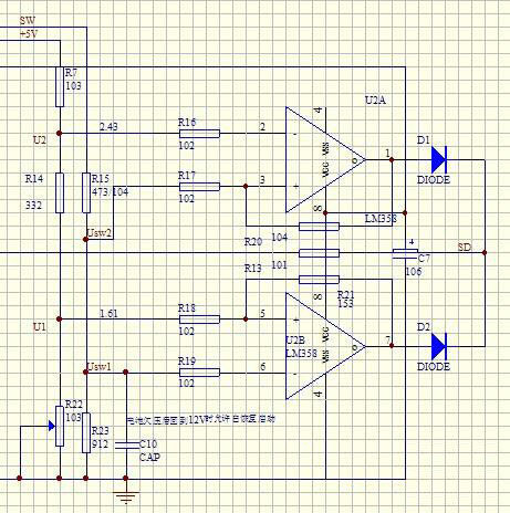 12v 300w uni-polar isolation of pure sine wave inverter Basic parameters Nominal power: 300W; continuous power: 250W; Peak power: ...
 12v 300w uni-polar isolation of pure sine wave inverter Basic parameters Nominal power: 300W; continuous power: 250W; Peak power: ...
600w Pure Sine Wave Power Inverter ...
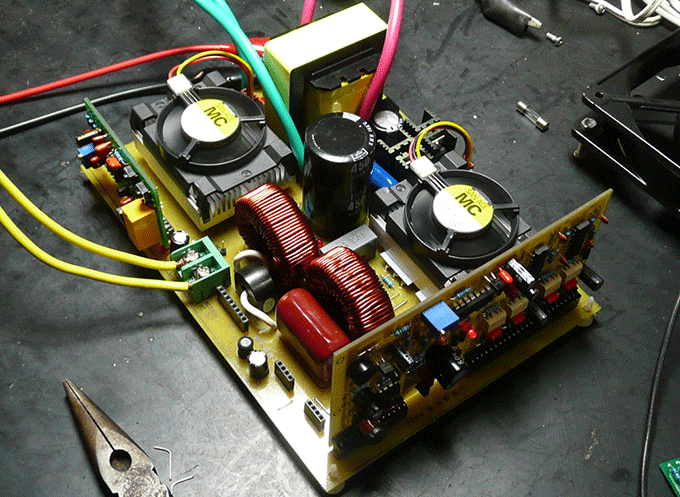 I spent nearly a month design a 600w pure sine wave power inverter. The machine has the following characteristics: 1. SPWM drive ...
 I spent nearly a month design a 600w pure sine wave power inverter. The machine has the following characteristics: 1. SPWM drive ...
1000w 12V DC Home Power Inverter ...
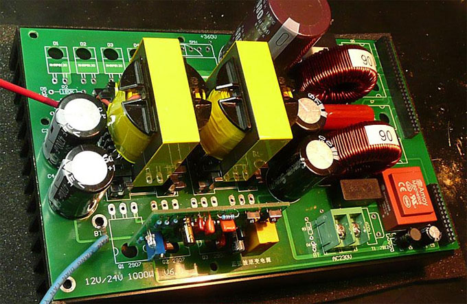 This power inverter is designed for 12v DC, but also can be connected to 24v DC, my goal is 800 watt, strive to 1000 watt pure ...
 This power inverter is designed for 12v DC, but also can be connected to 24v DC, my goal is 800 watt, strive to 1000 watt pure ...